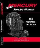
2002 Mercury OptiMax 250 Jet Drive Service Manual
Buy NOW!
FREE Shipping and Handling!

2002 Mercury OptiMax 250HP Jet Drive Service Manual.
Part Number: 90-888438
Starting Model Year 2002
Starting Serial Number 0E407100
Manual chapters:
250 OptiMax Jet Drive
- Notice
- Notice to Users of This Manual
- Cleanliness and Care of Mercury Jet Unit
- Page Numbering
- Service Manual Outline
Section 1A - Specifications
- Table of Contents
- Master Specifications
- Mercury/Quicksilver Lubricants and Sealants
Section 1B - Maintenance
- Table of Contents
- Specifications
- Special Tools
- Mercury/Quicksilver Lubricants and Sealants
- Maintenance
- Fuel System
- Spark Plug Inspection
- Battery Inspection
- Fuse Replacement
- Compressor Air intake Filter
- Flushing Cooling System
- Out-of-Season Storage
Section 1C - General Information
- Table of Contents
- Serial Number Location
- Conditions Affecting Performance
- Following Complete Submersion
- Model 250 Optimax Jet Front View
- Model 250 Optimax Jet Starboard View
- Model 250 Optimax Jet Port View
- Model 250 Optimax Jet Aft View
- Model 250 Optimax Jet Top View
- Mercury Jet Pump Starboard View
- Mercury Jet Pump Port View
Section 1D - Mercury Jet Installation
- Table of Contents
- General Information
- Installation Requirements
- Mercury Jet Drive Hull Dimensions
- Installing Jet Pump
- Bilge Siphon Feature
- Water By-Pass System
- Installing Powerhead
- Throttle Cable
- Oil Injection Set-Up
- Trim Plate Adjustment
- Exhaust System Installation
- Pre-delivery Inspection
Section 2A – Ignition
- Table of Contents
- Specifications
- Special Tools
- Coil Plate
- Solenoid Plate Model
- Theory of Operation
- Ignition Component Description
- Troubleshooting Without Digital Diagnostic Terminal
- Troubleshooting With the Digital Diagnostic Terminal
- DDT Functions – Optimax Models Software Version 1.0 ( P/ N 880118)
- Ignition Components Removal and Installation
Section 2B – Charging & Starting System
- Table of Contents
- Specifications
- Special Tools
- Battery Cable Size
- Replacement Parts
- Recommended Battery
- Battery
- Charging a Discharged Battery
- Winter Storage of Batteries
- Flywheel Removal and Installation
- Flywheel/Alternator
- System Components
- Alternator Description
- Diagnosis of Alternator System on Engine
- Alternator System Circuitry Test
- Repair
- Installation
- Alternator Belt Tension Adjustment
- Starter System
- Starter Motor
- Troubleshooting the Starter Circuit
- Starter Circuit Troubleshooting Flow Chart
- Starter Removal and Installation
- Disassembly
- Cleaning and Inspection
- Reassembly
- Starter Cleaning, Inspection and Testing
- Commander 2000 Key Switch Test
Section 2C – Timing, Synchronizing & Adjusting
- Table of Contents
- Specifications
- Special Tools
- Crank Position Sensor
- Throttle Cam Adjustment
- Throttle Position Sensor (TPS) Adjustment
- Idle Speed
Section 3A – Electric Fuel Pump
- Table of Contents
- Specifications
- Fuel Pump Assembly
- Special Tools
- Fuel Lift Pump Description/Operation
- Checking for Restricted Fuel Flow Caused by Anti-siphon Valves
- Checking Fuel Pump Lift (Vacuum)
- Fuel Lift Pump Disassembly/Assembly
Section 3B – Direct Fuel Injection
- Table of Contents
- Specifications
- Special Tools
- Air Handler
- Air Handler Components
- Vapor Separator Components
- Fuel Rails
- Air Compressor Components
- DFI Operation
- Testing Electric Fuel Pump Pressure Output
- Fuel Management Assembly Removal
Section 3C – Oil Injection
- Table of Contents
- Oil System Operation
- Oiling System
- Oil System Troubleshooting
Section 3D – Emissions
- Table of Contents
- Exhaust Emissions Standards
- Stratified vs Homogenized Charge
- Emissions Information
- Service Replacement Certification Label
Section 4A - Powerhead
- Table of Contents
- Powerhead Specifications
- Special Tools
- Cylinder Block Assembly
- Crankshaft, Pistons and Connecting Rods
- Expansion Chamber and Adaptor Plates
- Torque Sequence
- General Information
- Powerhead Removal from Pump Unit
- Exhaust Chamber Removal
- Powerhead Disassembly
- Cleaning and Inspection
- Powerhead Reassembly and Installation
- Reinstalling Engine Components
- Throttle Lever and Shift Shaft
- Powerhead Installation on Pump Unit
- Break-ln Procedure
Section 4B - Cooling
- Table of Contents
- Specifications
- Special Tools
- Model 250 Optimax Jet Water Flow
- Water Pressure Check
Section 5 - Jet Pump
- Table of Contents
- General Information
- Master Specifications Jet Pump
- Drive Housing Components
- Pinion & Impeller Shaft
- Nozzle/Rudder Components
- Servicing Stator, Impeller and Wear Ring
- Removing Jet Drive From Boat
- Drive Housing Disassembly and Reassembly
Section 6 - Color Diagrams
- 250 Optimax Jet Drive Engine Wiring
- 250 Optimax Jet Drive Typical Key Switch Wiring
- 250 Optimax Jet Drive Typical Remote Control and Dash Wiring Non-SmartCraft
- 250 Optimax Jet Drive Typical Remote Control and Dash Wiring with SmartCraft
- 250 Optimax Jet Drive Fuel & Air Flow Diagram
- 250 Optimax Jet Drive Water Flow
Manual is indexed with searchable text.
Manual has: 386 pages
Manual size: 15.70Mb
MP3 Players - Aircraft - Appliances - ATV - Cars - Computers - Database - eBooks - Jet Ski - Motorcycles - Outboard Motors - Personal Watercraft - Phones - Photo Cameras - Printers - Snowmobiles - Stern Drives
